So, I know that AI is basically rendering little tools like this useless, but sometimes I like to just have a simple ass spreadsheet where I can see everything that I want, all at once, without having to talk to a robot. Below is a tire size converter I built in Excel where you can enter the tire sizes on the left and it will tell you the diameter of the tires on the right. You can put in a bunch and have them all on the spreadsheet for easy viewing. If you mess up the formula, that’s on you! Just come back and get a fresh copy if you need to start over.
I also put a range in their starting at the Xterra stock size and going up to about the max that you can fit on the X without serious modifications.
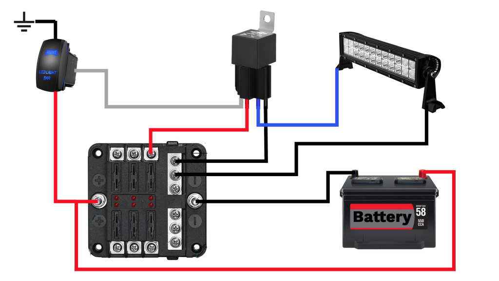
Today I installed a light bar into my Nissan Xterra (although this install is not vehicle specific). You can find the video below. I wanted to make sure the diagram was available somewhere other than YouTube so here it is.
I wanted to make this available on the site so it’s easier to see and find. Rather than pausing it on the video. So here you go! I confirmed that this is correct for the early year Titans and early year second gen Xterras and Frontiers.
This is a companion document to the RyTheCarGuy video titled THE WIRING EPISODE (How to VK Swap Episode 13). The document is at the bottom of this article.
https://youtu.be/yOEtsjdqnqM
This document is for the 2006 Nissan Titan to 2006 Nissan Xterra Wire Mapping. This includes the harnesses that are located in IPDM enclosure of each vehicle and is broken down into three main sections..
General Information
This document does NOT cover the wiring of the starter or alternator. Please reference the video above to gain a full picture of my methodology and a much better understanding of this document. The pinouts and mapping can be found on different tabs at the bottom of the sheet. Here you can find which connectors are wired to which, the size of each connector, and the Nissan color guide.
DISCLAIMER: Use this document for reference only. verify all pinouts and connections for your vehicle model and year. RyTheCarGuy is not responsible for any damage incurred to your vehicle based on the information provided in this document.
Connector Pinouts
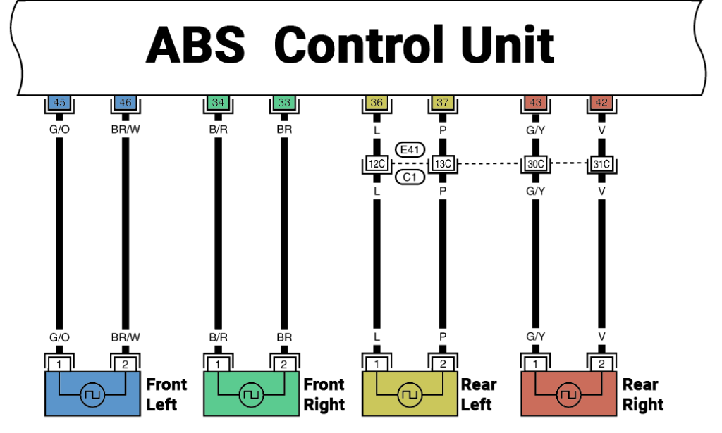
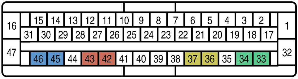
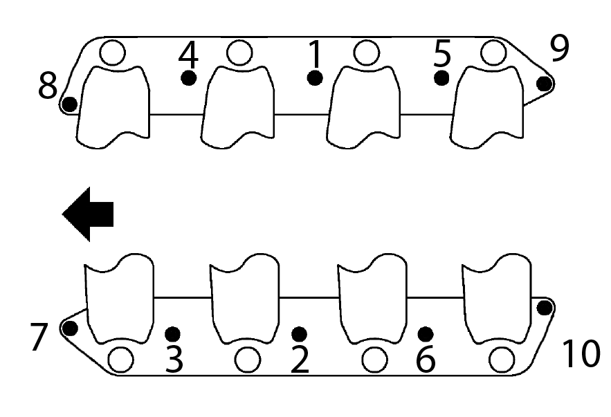
In this section there are three connectors from each vehicle listed out. E5, E2, and E19 for the Titan and F14, F32, and F33 for the Xterra. The corresponding connections are grouped vertically with the pin layout shown between them. For an example on the left of the sheet E5 and F14 are shown, those are (mostly) wired into each other and the pin layout of F14 is displayed between them. The pin layout is viewed from the terminal side, meaning the male side of the connection. The diagram is numbered as if you are looking into the open holes of the connector.
Connector Mappings
This section shows the mappings for each connector with the corresponding connector pin layout at the top of each mapping. The Xterra connectors are all listed numerically while the Titan pins are moved around to meet up with the corresponding wire on the Xterra side. The mappings are mirrored to display the most pertinent information aside from one another. To the right of each connection, you will find the left-over wires after each joining was complete. Some of these will be used in future steps of the project while others will be used or unused based on the features of each vehicle (IE, the water valve for the heater core on the titan does not exist on the Xterra so is unused. All wires were used on the F33 > E19 connectors. In the F32 > E2 mapping you will see that there are 3 pins that are highlighted in red. These are crossovers from other connectors. So pins 1,2,and 3 on F32 are actually connected to pins 6, 5, and 15 on E5, NOT E2.
Below is a no start condition guide for the Nissan Xterra. There are a couple very common issues with these vehicles, and I wanted to get a quick guide out there for people who have not delt with it before. This chart will grow with time and contributions from the Xterra community.
Below is a list of common Nissan codes and any corresponding Ry The Car Guy videos that attempt to address the issue. This is an active list and will be updated based on codes I address on my vehicles and create videos on.
Code
Description
Video
P1111
Intake Valve Timing Control Solenoid Valve Circuit Bank 1
Hey guys, this is a companion article to the video recently posted on RTCG 2 about my new (to me) 2020 RAM 2500. I state in the video that I will post a readable version of my window sticker and post so specs. So here they are. Also, if you are somehow here without seeing the video. I have it posted below for you.
Hey guys, as promised I wanted to get this cost break down out to you so you can see exactly what I spent rebuilding my VK 56. Here is a quick guide/tips on using the spread sheet.
Not everything on this list is required – I bought some items I could have lived without and I brough items that you might think is a waste. Conversely, I may have bought items that I consider optional that you might consider required. I used Column H to mark items that I considered optional/required
I broke it out by phase – Phase 1 was engine removal, phase 2 was the rebuild, and phase 3 was engine reinstall and first start/break in.
I did not buy all of these items for the rebuild. I already had a lot of it. I used the “new to me” column to determine my cost. You can do the same. You can put a capital X in each row that’s new to you and see an estimated cost to the far right.
The far right side – Scroll to the right and you will see the cost break down by type of item (Tools, consumables, and parts) as well as a total cost.
This article is a supplemental document to the video listed below.
https://youtu.be/EgR8yRR5tm0
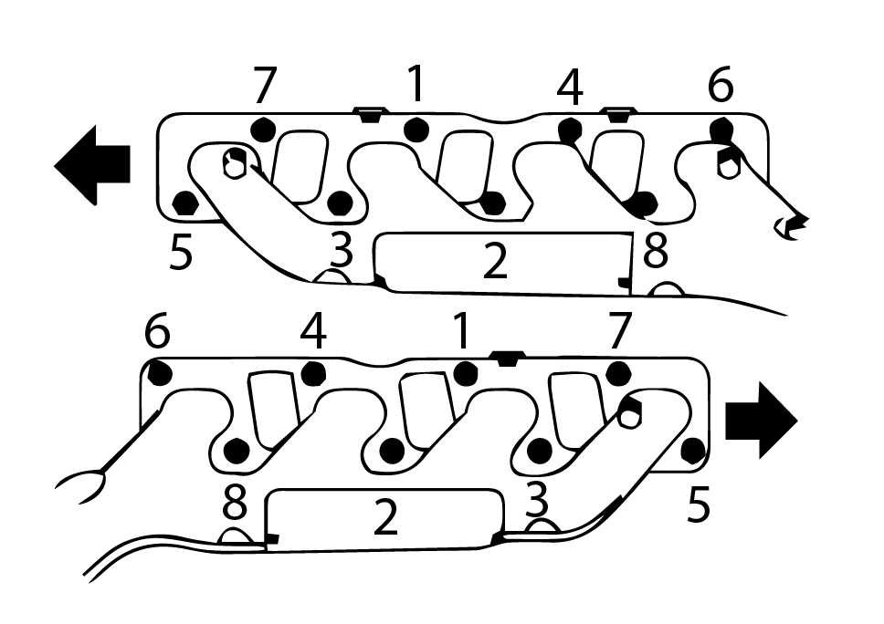
The below is in two sections first is an alphabetical list of all the torque specs I could find pertaining to the engine install. Second is a list of diagrams for the items that require a particular toque sequence. I recommend using the search function of your browser to quickly find what you are looking for. Reach out if I missed anything.
* All specs are in foot pounds unless otherwise noted.
Part
Torque (ft-lbs)
Air Conditioning Pump (cross pattern)
45
Alternator to lower bracket
16
Alternator to upper bracket
48
Cowl Mounts
51
Engine Mounting Bracket to Block
65
Exhaust Manifold
251
Exhaust Manifold Heat Shields
51 in-lbs
Front Cross Member
96
Front Drive Shafts (line up paint makers)
54
Front Final Drive (Differential)
135
Front Final Drive (Differential) Skid Plate
73 in-lbs
Front Propeller Shaft (Drive Shaft) (line up paint makers)
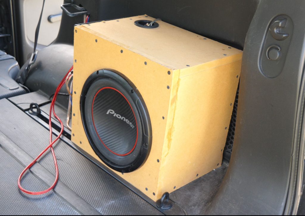
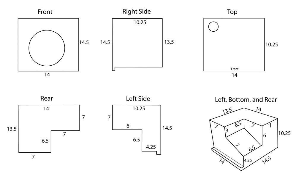
A long long time ago in a city far far away I made a box for a subwoofer that fit perfectly in my Xterra. I didn’t make a video on it because I was not at the point in my YT career that I was making a video on everything that I do to my Xterra. However, since I made it, I have gotten the occasional “how did you build that box?” comment in videos where you can see it. That led me to make a quick video describing how I did it (which can be found below). In order to make very clear how I accomplished this I also took measurements and drew out all the dimensions on a guide. Below you will see the image I created along with a link where you can download a printable PDF version.